Hello Everyone,
I'm quite intrigued by this project, and currently decided to try my hand at the software design with a caveat:
I'm writing a 3d simulation system of the track/robot in java.
The plan is, it is generating a 3d track, and using two viewports, one to be exported as a camera device, and the second to monitor an overhead of the function of the race code. I may need a little help to emulate the connection if running the python code against it, which is where this request comes in, to help fill in my knowledge of how the I/O goes in/out of the python library.
Some features I'm planning:
- Path Based Track
- Configurable Width
- Adjustable Simulation Motor Speed
Once I've got something functional over here, (I spent last night on math equations for the track generation), I'll be posting this somewhere for the community here to take and help. Hopefully, if I can complete this in a timely manor, it should help with everyone who cannot get their hands on the hardware to still have a chance to tune, learn, and be competitive.
Please feel free to give suggestions. I will be updating as I progress.
Very cool computernerd486, this would be very helpful in preventing sending over your bot code and ended up wiping out before finishing the first lap :)
Are you going to be hosting the code somewhere we can download/contribute to while you're working on it?
At the moment the code we have has a thread which reads camera frames from the
cv2.VideoCapturemodule.This thread then passes the data to a second thread which does the image processing on the frame.
When the image processing has completed it passes its results (offset, angle, et cetera) onto a third thread.
This thread runs some filtering and a PID loop to determine the final speed / steering output for the robot.
The speed and steering are then converted to motor speeds and given to the
ZB.SetMotor?functions to change the motor output.Next to all of this is a settings file which can be used to adjust / tune the processing and control code.
Currently we check if the file has been updated while the code is running and reload the settings if they have been changed.
This allows us to tweak settings while the processing is running, I presume this will be useful when simulating as well.
We are looking at the best way to re-structure this so that it is easier for people to pass in a folder of images so that they can test the image processing without needing a YetiBorg.
The current plan is to put the image processing and the control loop code into a separate module so that the main script is just responsible for managing threads and passing data between them.
This would allow a different main script to be used which looks at files instead of the camera.
Do you have any suggestions on what would help with running the code in a simulated environment?
The grand scheme of what i'm doing is to hopefully make it as seamless as possible. There's a little bit of testing here to make sure it works, but I'm almost positive there's a way to make the java program I've got steam out video.
That reading the images from a folder seems like a interesting idea, that might work well enough. Its heavy handed, I write out an image per update, and the program code picks it up to process.
Progress so far is below, the first (white background) shows the bulk of where my time went. I have the center line as a path of points defined in a list, and it calculates out the side points and averages the incoming and outgoing angles to bisect them.
The second screen is the progress on the 3D simulation part. The upper left corner is the view from the YetiBorg's perspective, the rest is a top down view of the track. That perspective viewport is what will be exported.
A couple questions:
Your simulation is already looking really good ^_^
We have tried to focus on processing speed as the Pi Zero has limited processing power compared to its bigger brothers.
What we have so far is working from a 160 x 120 image at a 5 fps rate.
The processing seems to handle about 7 fps, but we ask the camera for less to ensure the processing completes on time.
We do not have any detailed charts on the motors as far as I remember.
From a quick measurement the YetiBorg travels at about 1.1 m/s when going straight forward.
I will have a look what data sheets we have on the motors when I am back in the office.
The lights follow this pattern:
At this point the robots turn their ZeroBorg LED on so we know they can see the lights
At this point the robots can go
The exact times are still being written into the rules, but the final red to green will have some random delay between two values.
The lights are at the top of the camera shot, roughly at 50% X and 27% Y.
The YetiBorg can see a lot less of the track then your model shows at the moment, he is much lower down.
If placed in the exact center of a coloured line he can only see that colour for something like the bottom 5-10% of the image.
We also crop off the top 43% of the image, this sees about 2/3 of the outer wall in the horizon once cropped.
The outer wall is black and 200 mm high if memory serves.
The inner wall is also black and either 200 or 100 mm high.
I will grab some shots from the YetiBorg at different points around the track for reference, and some shots of the lights from the starting grid.
I will also take some measurements to try and give a precise camera position for the viewport.
Camera position:
41.5 mm from the camera centre to the floor.
Mounted in the centre of the robot.
Pointed ever so slightly downward, about 3°.
The only data sheet we have for the motors is here: http://wzh001.gotoip55.com/upload/file/ZGA20RU%20&%20ZGA25RQ.pdf
It is the 6 V motor with a 180 no-load RPM.
For the racing we will be running them slightly over-voltage, about 8.2 V.
The tyres have an outer diameter of about 84 mm
I have taken some static photos around the track to give an idea what the real images look like.
One is at the actual 160 x 120 resolution, the rest are at 800 x 600 so you can see some more detail.
They are the actual orientation seen by the camera, the first thing the code does is to rotate them 180° :)
An image from against the outside wall facing the inside wall.
Thank you for all those captures and the extra information, that will help a bunch. I'm getting closer with the broad strokes of coding, so that data is at a great time as I prepare to start using actual numbers.
An extra question about the video capture you have setup. Are you using the opencv framework?
I think I can export a rtp/rtsp stream with little difficulty, and the python cv library looks to support that directly.
The remaining question is still how to get the motor controls back and forth. Is the YetiBorg motor I2C controlled? There might be an angle to use that as the intercept point. The control of these, is it safe to assume that the motors are operated in pairs left/right instead of individual?
Not to disappoint, here's a little bit of progress I've made.
Which to show this progress, I've provided a video on YouTube.
Simple AI on Simulation (via YouTube)
There is still some items to do to make this closer:
Hopefully I'll have this stable soon and can hand it over to the FormulaPi team for initial testing with their alpha control code and compare results with a real life YetiBorg.
That video is awesome, it is starting to look like Formula Pi the video game :)
We are using the OpenCV libraries to get the feed from the camera at the moment.
This is the actual code we are using to grab the camera frames.
The motors are driven using our ZeroBorg board.
The commands are sent to the board using I2C via the
ZeroBorg.pylibrary.I can think of two easy ways of intercepting the final motor speeds:
ZeroBorg.pywith a dummy version.This can transmit the values back to the simulation instead of to the motors.
The functions which will matter to the simulation are:
MotorsOff,SetMotor1,SetMotor2,SetMotor3,SetMotor4, and maybeSetLedif you wanted to check light detection.If there is a ZeroBorg attached at the time the code can just run normally.
You can then interrogate the motor speeds at regular intervals using:
GetMotor1,GetMotor2,GetMotor3, andGetMotor4.Alternatively if you have a way of intercepting the I2C messages themselves then each of these calls has a command code followed by a single byte value.
You can download the
ZeroBorg.pylibrary from here:http://www.piborg.org/downloads/zeroborg/examples.zip
The commands are all fairly simple, it should not be too hard to interpret the I2C values or send the data elsewhere.
The control loop currently works out the power to output as:
Speed between -1 (full reverse) to +1 (full forward) with 0 being stopped.
Steering between -1 (full left) to +1 (full right) with 0 being straight forward.
The left and right sides are driven as pairs, we have not found any reason to control all four motors independently when racing.
The actual conversion to drive outputs is currently like this:
    def SetDrive(self, speed, steering):
        global ZB
        # Make sure speed and steering are within limits
        if steering < -1.0:
            steering = -1.0
        elif steering > 1.0:
            steering = 1.0
        if speed < -1.0:
            speed = -1.0
        elif speed > 1.0:
            speed = 1.0
        # Final steering corrections
        steering *= Settings.steeringGain
        steering += Settings.steeringOffset
        # Determine the individual drive power levels
        driveLeft  = speed
        driveRight = speed
        if steering < -0.01:
            # Turning left
            driveLeft *= 1.0 + steering
        elif steering > 0.01:
            # Turning right
            driveRight *= 1.0 - steering
        # Set the motors to the new speeds
        #print 'D %.3f | S %+.3f' % (speed, steering)
        #print driveLeft, driveRight
        ZB.SetMotor1(-driveRight * Settings.maxPower) # Front right
        ZB.SetMotor2(-driveLeft  * Settings.maxPower) # Front left
        ZB.SetMotor3(-driveLeft  * Settings.maxPower) # Rear left
        ZB.SetMotor4(-driveRight * Settings.maxPower) # Rear right
The values we are currently run with are:
Settings.steeringGain = 2.0- At 1.0 this allows full breaking on the turning side, at 2.0 this allows reverse powering on the turning side.Settings.steeringOffset = 0.0- Allows people to tweak if the YetiBorg drifts left / right, the house robots will be mechanically aligned so that this is unneeded.Settings.maxPower = 8.2 / 8.4- This stops the motors using 100% of the battery, otherwise the 5V regulator can struggle when the battery starts to get flat.As a final thought this actually looks more comprehensive then the simulation mode we were intending to provide.
Would you be happy to make this a part of the released software for competitors to test their code?
I'd be glad to have this as sanctioned software that you guys distribute. A major detractor for any competitor is lack of confidence in code and inability to setup a full size test on physical hardware. Hopefully this will help fill the gap.
You've supplied a ton of good info with these posts, and I've started hardening/optimizing/cleaning code in preparation to start using those numbers. This coding is quite fun for me, and there are few chances to mix hardware and software (the end result of all of this).
There isn't any visual updates as of yet tonight, minus use of a new track texture. Key things I've done:
It has been running smoothly at 60fps (the target cap) on my desktop (4 core / 8 thread xeon @ 3.3Ghz, 16GB ddr3, twin gtx 660ti's). Granted, my desktop is a touch over powered for most things.
I'm excited to see the progress you guys have running the YetiBorgs around the track. I can't wait to get to the point where we can compare this to an actual run. Hopefully I get some pi hardware here soon, It seems like that cable for the camera to the zero is out of stock most places on this side of the pond, I may just pick up a regular pi 3 B for some fun, which may be a touch easier to dev on anyway.
I'll be working on track loading/saving/editor here next, so that I can push in actual dimensions. For scaling purpose, do you have the overall width/length of the Yetibot and the tyre width available?
I have taken some measurements from a YetiBorg for you, diagram attached below.
I think the best way to interface the simulation will be via network / streaming.
That way the processing code can be run either on the same machine, or on a Raspberry Pi connected to the network.
With that approach it should be possible to see if the code works on an actual Pi at a fast enough rate.
I wonder if the simulation could have two different modes when testing code:
Puts out frames at the rate the code will ask for them from the camera.
Puts the frames out at a higher rate (60 fps maybe?), attempts to measure the actual response rate coming back from the control
The biggest challenge we have had has been keeping the performance reasonable.
The same code we have running at the moment can handle 30 fps fine on a Raspberry Pi 3, but on the Zero we struggle to get more than about 7 fps reliably.
What we have found is that the control is better if it is slightly less accurate but gets results quicker.
The first version used a more precise algorithm and a higher resolution at about 2~3 fps.
This was problematic for cornering, especially on the S curve where it tended to clip the wall :)
I suspect that lane detection algorithm that they are using something similar to this approach
https://www.researchgate.net/publication/276344687_Design_and_Implementa...
I've completed a little bit more on back end cleanup, and started converting to real measurements.
To the exciting bits of progress updates:
I've taken one of the screens you provided and did a side by side of the output of this, it looks pretty close.
I have a pi 3 b on its way to me, which I should see Friday. That make this more interesting, i'll be able to work on a connector setup between the simulation on my pc and the pi to see how code runs there/back and forth to the simulation. Being able to peek at what the camera is actually supplying may be useful to "emulate" it.
I'll start working on getting a test prepared with the video stream output, and hopefully be able to send over something that runs a static image at least for testing the image part of the connector.
The simulation output is really looking good now :)
It is quite interesting how much brighter the lane colours are in person compared with what the camera can see.
Let us know if you need any help getting the Raspberry Pi side of things going.
Before using OpenCV we setup the Video4Linux driver for the Pi camera with this command:
sudo modprobe bcm2835-v4l2This can be put into the script itself as:
import os os.system('sudo modprobe bcm2835-v4l2')I may need some help on the python side, it's not a language I use very often, if at all. Last time I had used it was a load testing bot net at work to harden our web servers, and that was two years ago. Using the stock camera code examples should be 90%, and at least let me make sure the connection works, correct?
I would have thought so, yes.
I've made some additions on the streaming side to output a png at 10 fps to the file system (It just overwrites the same file). This is mildly heavy, but can work as an interim while I work to get the rtp stream working. It does write upside down, the same as the camera picks up.
I have both image size and fps of the out as configurable properties.
The next thing for me to work on is updating the math for the positioning based on two motor inputs, and to read from either a) text files and/or b) a socket style IO.
After the motor math and reading is done, I'll be able to send an alpha version over for a sanity check.
I think we can probably read in the image base on its time-stamp like this:
import time
import os
import cv2

imagePath = r'somefolder/image.png'
oldModificationStamp = 0

while True:
    newModificationStamp = os.path.getmtime(imagePath)
	if newModificationStamp != oldModificationStamp:
		frame = cv2.imread(imagePath)
		if frame == None:
			# Could not load the image for any reason
			time.sleep(0.01)
		else:
			oldModificationStamp = newModificationStamp
			# Pass frame to the processing stages here
	else:
		time.sleep(0.01)
10 fps will likely be faster than the processing will respond anyway at the moment, it should be fine for testing the current code.
As for the output I think we will replace
ZeroBorg.pywith a dummy version which reports status after the all the motors have been set.Both text file output or socket I/O will be fine for this.
At some stage we will try and gather some data on how the YetiBorg actually behaves for given inputs.
In particular the turning circle is wider than expected when running one side fully on and the other fully off.
We were thinking about marking a grid down and filming the movement at different settings.
Sorry about the lack of updates here for the past few days, I've been at a bit of a standstill on some of the streaming and connection pieces.
Good news is I think i have a good connection scheme going here now. Since the filesystem approach was a touch slow and resource heavy, not to mention there are issues running the simulation remote from the Pi hardware, I've gone with an HTTP based request.
The python which is running on my Pi, uses the cv2.VideoCapture to pull it in this way, which should be almost identical to how you read the camera normally.
Simple image grab from sim, python running on Pi:
import cv2

cv2.namedWindow('image', cv2.WINDOW_NORMAL)

cap = cv2.VideoCapture("http://192.168.1.144:10000/view.png")
if( cap.isOpened() ) :
    ret,img = cap.read()
    cv2.imshow('image',img)

cv2.waitKey(0)
cv2.destroyAllWindows()
This way you can adjust the pooling rate on that side, or try and run it as fast as you can. The images are running at a 60 fps update on the sim, with a 20ms update period of position/direction. There will be a configuration panel on the simulation screen to adjust output image size/flipping/port, the references are coded in the background, but no interface to change them yet.
The interesting thing I've done is for motor control. They can be controlled via url parameters, this is technically the same call as the image, but can be made separate (will still return the image, just discard it)
The m1 and m2 are parameters that can be from -1 to 1, aka -100% to +100%.
I'm still going to work on optimizing this out to use rtsp/rtp, but that was running into a bunch of problems and landed the requirement of reading the rfc for RTP and RTSP.
Currently, I'm working on updating the positioning to be based off the dual motor speed, differential drive, equations. I had to call a mechanical engineer friend to see if he has any idea how to explain them, its a touch above my current math ability. Once that is done, this should be ready for a test.
It all looks like it is coming together nicely.
We got around to restructuring the code this week, now the image processing is in a separate script from the thread management code.
All of the code which talks to hardware (camera and ZeroBorg) is kept to the management script which allows it to be replaced with a simulation version without altering any of the scripts which do the hard work.
As a test we have a testing script which can either:
What we intend to do is make a second testing script which connects your simulation with the image processing routines.
The method you have already will work nicely with this, but it should be straight forward to change to a different scheme later as well if you still wish to do that.
I will probably put a toggle in the script to switch between limiting the frame rate to the one in the settings file, or to override and load frames as fast as the image processing can handle for speed testing.
It will be interesting to see what the speed differences are between a normal desk PC and the Raspberry Pi Zero :)
The current script makes a single call into the processing for each frame that comes in, it also gets a single callback for motor settings when the processing is done.
This will make it easy to call a URL when new motor speeds have been chosen.
The nice thing about this is that the simulation mode can still allow the image processing to work with multiple threads.
This will be useful as we are thinking about running a faster class in the future using Raspberry Pi 3s which need multi-threaded processing to make full use of the quad core.
We can also alter the image prior to processing if there is any need to in the future.
Finally there is an ability to enable images from stages during the processing to be displayed as they are generated as well.
Simulating motors will probably still need us to get some kind of characteristics of the robot itself.
The biggest difficulty in modelling this will be that at 0% the motors free-wheel rather than breaking.
This means at Left: 100%, Right: 0% the YetiBorg moves in an arc to the right.
I would guess that arc has a radius around 1~2 meters, but we have not measured it properly.
What we currently do is use some reverse throttle to act as a break to turn tighter.
For example Left: +100%, Right: -30% still makes an arc, but a much tighter one.
If you get to full reverse drive, e.g. Left: +100%, Right: -100% the YetiBorg will spin on the spot.
We mostly use this for spinning around when we face the wrong way.
That's exciting with the code restructure, sounds like this should be a good pop in/out.
I do have it functioning with the dual motors, and it is doing the forward/spin/list direction when one side off. It's getting closer to the point at handing over, the additions made so far today:
I'm meeting my engineering buddy who has the differential drive equations figured out, at the bar tonight to talk trig and calc. Hopefully I can get a more exact equation, or at least verify my current one.
Still to do:
I'll send an email across the contact form.
The alpha release has been packaged and is ready for testing,
I've spun together a quick driver that uses the HTTP interface to pull the image and send the motor speed using an xbox controller to show the motor reference on the screen.
It's displaying a sliding bar for speed, green for forward, red for reverse.
Progress Video:
Alpha Demo
The progress you have made over the weekend is awesome, we cannot wait to see what it will make of our code :P
I have sent you a reply by email to discuss how we should share the code for testing.
Looking good Tim, can't wait to take your sim for a test drive :-)
For those of you following along, I have passed the initial alpha for the FormulaPi team, some things that came out of a quick test was "instantaneous acceleration" issue, and a camera flipping issue.
I've addressed both, now with a linear acceleration/deceleration delay. This makes it MUCH easier to control via my xbox controller. This comes with an addition to the UI, it shows the requested speed, vs actual motor speed. The max acceleration/deceleration is a configurable parameter now. I've included a screenshot to show this.
With the help of the FormulaPi team, I hope to have this validated to a usable first order approximation, and available at the point they release the control code. Those guys deserve a lot of thanks and respect for their hard effort making that control code into an easy to pick up, accessible library. The dual motor control and math is difficult to grasp unless you're well versed in trig, especially to make it reliable for a robot like this.
Sounds like a good starting point form modelling the real YetiBorg.
We will have a play later and see what values behave closest to the real robot.
The end result is a much more accurate simulation of how our YetiBorg is driving.
This is what we see running the real Race Code:
I have been working on a few more additions with the feedback of the PiBorg Team. It has been great working with everyone to help make this as beneficial to the community as possible.
Additions Include:
The plan is to release this alongside the official release of the base code from the PiBorg team, and have the output very close to the actual YetiBorg's response. So far, its close, with a few more fixes and tweaks to perform.
The Light bar has been added! They don't have the "bleed" that the actual LED's do, that may come soon, but it should be enough to pickup the indicators from.
A couple new features being worked on:
It's coming together in the final stretch. There's more math to be had here, especially to try and get the motor control to a better state, it still has some oddities that I have been working with the FormulaPi team to help resolve.
Hi,
Great work with the simulator, looks great!
I've downloaded the race code and was trying to run a simulated race to test this, even without any development to the race strategy.
I didn't find a way to start the simulator. I see references to the IP and port from SimulationFull.py, but I didn't find any code that will listen in that port.
Is it already available in the race code, or is it available somewhere else?
Thanks,
Jorge
The simulator is not quite there yet, computernerd486 is still putting the finishing touches on for the first release.
We have been using the simulator in an unfinished state for both testing the simulator and testing our own code.
SimulationFull.py is the correct script, but there will be some minor alterations to it when the simulator is ready.
We will make sure everyone knows when the simulator is ready to be downloaded :)
Ok, thanks for the confirmation. I'll wait for it, looking forward to playing with it :)
The first release of the simulation is now in with the standard race code.
The simulation itself is in the
Simulationdirectory.At the bottom of
Guides\Simulation modes.txtthere is a section about the sequence for starting a race.The simulation in action:
The Raspberry Pi side running the processing with SimulationFull.py:
To get this screen output modify the settings below to match in SimulationFull.py:
To overcome the 'fudge' factor required in the working with the lights bar would it perhaps be possible to use an image of the real lights in the various states rather than attempting to emulate them—I realise that this might be over simplifying things, but as it is a scene element that doesn't really require any three dimensional aspect, could it provide a work around?
That is a really good suggestion, I have just tried a quick edit and it appears to work.
I have changed the
lightbar_soft.pngby using a cropped copy of the green and red photos, see attached.I then commented out these override lines in
SimulationFull.py:This seems to work nicely and is a little more accurate for those developing their own detection.
It also emulates the halo problem whereby the actual point the LED is at looks almost white.
Are you happy for us to make this change official Tim?
It looks much better! I'm completely happy with that, i'll change the image to that in my repository, you can change it on yours.
This is why I've tried to keep it as robust as possible, keep Amy improvement suggestions coming!
I have made the change and removed all of the override code on SourceForge.
I have also emailed everyone to let them know ^_^
I'm very pleased to have been a help — it looks good.
I know a lot of people may have issues with having a monitor, usb otg dongles, keyboard, mouse, when the pi zero is so cheap by itself, but the supporting items can be expensive. I've got the interesting case of currently traveling and its bare minimal stuff I'm carrying with me.
You can develop on the pi with just a usb micro cable!
I followed the instructions to setup the pi to be an otg ethernet device.
OTG Setup
Then I did a reverse port forward to make the 10000 port for the sim local. So the software on the PI would connect to 127.0.0.1:10000
You can use sftp to transfer data across if you want, that is how I moved my driver program over.
Attached is a picture of the setup running successfully.
That is a really cool idea, we never thought of that!
The reverse port forward is a nice touch, saves the need to keep changing IP addresses in the script for any reason.
I know you've been using xforwarding too, try the -Y option, and see if it cleans up the view delays for you.
-Y Enables trusted X11 forwarding. Trusted X11 forwardings are not subjected to the X11 SECURITY extension controls.I did not think to try that, it will be interesting to see if it has any effect.
There are so many configuration options it is hard to remember what they all do :)
I presume this is the same as the "Bypass authentication entirely" option in PuTTY.
I will give it a go when I get a chance later in the week.
I have been trying to run simulation on my Raspberry Pi 3 model B (ie. java -jar Sim.jar), however I get the following error message:-
Exception in thread "main" java.lang.UnsatisfiedLinkError: Can't load library: /home/pi/formulapi/Simulation/natives/linux-armv6hf//libgluegen-rt.so
Any ideas where I can find the missing library?
Nb. using java version "1.8.0_65"
The simulation itself has issues running on the PI, the way to test is to run the simulation on a full computer, that is connected to the same network as the PI.
The opengl that is available on the pi does have issues that i've seen, and have not successfully ran it there yet. Yes, you will get some network lag, but it allows the PI to be dedicated to running the driving code. Revisiting that is on my list of todo, but the only way I can say it will work for sure is to do the split computer running sim/pi running race code.
If you do want to try to make it work on the pi3 itself, you can add in the missing native library by downloading the jogl all-platform library (Jogl Library) and taking the glugen-rt-*armv6hf, jogl*arm6hf libraries into the sim_lib directory.
After you get past this it will be interesting to see how the simulation actually works on a Raspberry Pi.
In case you are not aware the OpenGL drivers for the Pi are currently experimental and need to be enabled manually.
If you go to this post and scroll down to "One more thing…" it tells you how to enable the driver and check it is working correctly:
https://www.raspberrypi.org/blog/another-new-raspbian-release/
We still would suggest using another machine to run the simulation for testing so that it does not hurt the performance of anything.
If it does work though it would be awesome, it might even be tempting to have two Pis running via an Ethernet cable :)
The most current addition I've been preparing is the lap timer. It'll hold you last 5 laps covered, and show the current lap's time.
I've been working on running the driver program on either the Pi3 or the PiZero, hence the OTG update above, and trying to make sure the simulator at a stable state across networks. I've done wifi to the pi3, and the OTG ethernet testing to both.
Also, my trip this past weekend brought me to a Micro Center, where two pi zeros, the camera cable, and an 3 way accelerator chip, and a couple 8 gig sd's. I'll be hooking that up to the zero for data aggregation on the acceleration, and that should allow me to tune the simulation the best for the motors (whenever access to physical hardware is available).
Hopefully there's a few goodies coming down the pipe on the sim. If there are any specific issues which are evident, please report them so I can take a look and improve the system.
I'll be revisiting allowing for a higher res video out (which should solve some cutoff issues on small monitors too), and an update to the video stream to remove the hits/misses that may happen at higher speeds.
It sounds like the simulation is getting really polished now.
It will be interesting to compare lap times with the real YetiBorgs.
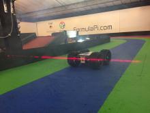
We are going to fit our laser timing rig at some point so that we can tune the speed of the YetiBorgs.
The idea is that we will calibrate the house robots so they all mechanically drive straight.
We will then tune their speeds to the same level with a special load of firmware for the ZeroBorg which limits the maximum power output.
After some experimenting last week I can confirm that playing with the PID values more or less behaves the same as the real robot.
Hopefully we will be able to ship YetiBorgs reasonably soon.
We have just sent someone off to pick up the chassis plates today.
They are the same guys we usually use to get metal cut so we know what to expect from them :)
All we are really waiting on now are the wheels.
We have had some arrive already, but we still have about 200 to be delivered.
Once they are in we can start sending everything off.
Hi,
at first great thanks for coding the Simulation!
But I have huge problems starting the Jar file on any machine with OpenGl < 3.2 because it uses glframebuffertexture and older openGl only provides glframebuffertexture2D which should also be sufficient i think? I can only run the program on a slow wimpy intel Tablet, this is very frustrating to use. Would love to use it on machines with older graphics cards. How could I do the adaptation myself? any Java pro out there who could take a look at?
Hi Flip,
Can you give me a little info on the machine you're trying to run this?. What versions of opengl you do have support for, what os/video card? I am doing some trickery with that glframebuffertexture, but I may be able to code around it.
Hi,
not working: Core 2 Duo or Intel I5-2520M (HD-Graphics 3000) ( openGL 3.1, some other extensions but jogl reports i cant find the neccesary opengl functions such as glframebufferaddtexture)
working: intel X5-Z8300
all running the same newest build of windows 10
Thanks in advance
Flip
Pages
Add new comment